Electro-Cap 8-ch (10-20)¶
Eight electrodes on standard 10-20 sites — Cz Pz P7 P3 P4 P8 O1 O2 — wired to an OpenBCI Cyton, with reference and ground on the earlobes. This is the eight-site set a good many small clinical and teaching caps ship pre-wired, the lab's Electro-Cap among them, so the whole montage goes on by fitting one cap and plugging eight leads into holders that are already in the right places.
It is the widest of the toolbox's three 8-channel carriers: the vertex, the parietal row out to the posterior temporals, and both occipital sites. That is its reason to exist and also its cost — see §1.
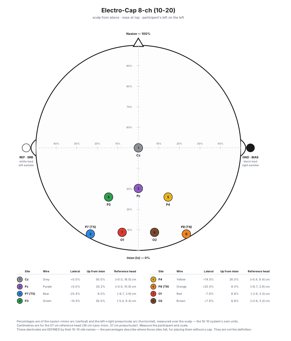
1. The montage¶
| Ch | Wire | Site | Lateral | Up from inion | 57 cm head |
|---|---|---|---|---|---|
| 1 | Grey | Cz | 0 % | 50.0 % | on the midline, 18.0 cm up |
| 2 | Purple | Pz | 0 % | 30.2 % | on the midline, 10.9 cm up |
| 3 | Blue | P7 (T5) | −23.4 % | 8.0 % | 8.7 cm left, 2.9 cm up |
| 4 | Green | P3 | −14.5 % | 26.0 % | 5.4 cm left, 9.4 cm up |
| 5 | Yellow | P4 | +14.5 % | 26.0 % | 5.4 cm right, 9.4 cm up |
| 6 | Orange | P8 (T6) | +23.4 % | 8.0 % | 8.7 cm right, 2.9 cm up |
| 7 | Red | O1 | −7.9 % | 8.8 % | 2.9 cm left, 3.2 cm up |
| 8 | Brown | O2 | +7.9 % | 8.8 % | 2.9 cm right, 3.2 cm up |
Board order runs midline first, then left→right across the parietal/temporal row, then the two occipitals. Channel colours follow the Cyton's ribbon cable (§3).
P7/P8 are the sites your cap calls T5/T6
They are the same two electrodes. T5/T6 are the pre-1991 10-20 names, and a cap of this vintage is silkscreened with them; P7/P8 are the current names, and they are what the toolbox records. That split is deliberate, and it is one-directional: the figures and this document print both so you can find the hole on the cap, while every recorded label, every BIDS _channels.tsv row and every plot legend says P7/P8 — the name MNE can place, that ssvep.spatial already knows, and that a reader outside this lab will not have to look up. Recording T5 would buy the operator a familiar string and charge every downstream tool for it.
The site name is the definition — the percentages are not
Exactly as for the Occipital 10-10 montage: P3 already says where the electrode goes, so the percentage and centimetre columns are descriptive — where those sites fall on the nasion→inion and left→right preauricular arcs of the standard_1005 template head, computed by scripts/build_montage_figures.py for placing the montage without a cap. The toolbox records no position_pct for this montage, because a second statement of the same fact is free to drift from the first.
Cz landing at exactly 50.0 % of the naso-inion arc is the check that the template and the arithmetic agree — it is the vertex by definition.
What this montage is for, and what it is not for¶
Use it when the run wants coverage: alpha and resting-state work, posterior ERPs, a teaching session, a quick screen on a participant where fitting one cap beats measuring eight free electrodes onto a scalp. It is also the only carrier here that a lab with a stock 8-site cap already owns.
Do not reach for it when every channel should be buying SSVEP. Only two of its eight sites — O1 and O2 — are in this toolbox's validated occipital-8 (ssvep.spatial.OCCIPITAL_PRIORITY, first eight entries, the set that decoded best on sub-904). Pz, P3 and P4 are in the extensions that list falls back to only when it needs more than eight channels, and Cz, P7 and P8 are in neither — they are a long way from visual cortex. That matters more than it sounds, because calibration-free CCA/FBCCA has no channel-selection mechanism of its own — the sub-904 result behind ssvep.spatial is that non-occipital channels give it room to fit its sinusoid templates to noise (docs/DESIGN_PRINCIPLES.md #8). The decoder's automatic occipital-ROI restriction does not engage here: it keys off montage size (spatial.BIG_MONTAGE, 16), on the assumption that a small array is already occipital by design — true of the other two 8-channel carriers, and not true of this one. So all eight channels reach the decoder, including the three that are not looking at the stimulus.
That is accepted behaviour, not a defect to work around (Aaron, 2026-09-17): record on this montage and decode the eight channels as they come. The teaching lab has Electro-Caps, so data on this montage is expected, and it is what will settle the open question — whether restricting to O1/O2 actually beats all eight (two channels may well be worse), or whether the five-channel O1 O2 Pz P3 P4 set is the right middle. #220 tracks making the gate decide by composition rather than channel count, once there is a recording to test it against. Nothing here needs doing at the bench.
For an SSVEP run whose result has to be as good as eight electrodes can make it, use the Occipital 10-10 montage (standard sites, still cap-placeable) or the free electrode occipital montage (denser over the pole, non-standard names).
2. Placing it¶
With a cap — the intended route, and the reason to pick this montage at all. Fit the cap by the usual procedure (Cz at the crossing of the nasion→inion and preauricular arcs) and plug the eight leads into the Cz Pz T5 P3 P4 T6 O1 O2 holders — those being the cap's own labels for the sites §1 lists as Cz Pz P7 P3 P4 P8 O1 O2. Nothing to measure beyond the cap fit itself.
Without a cap, mark the standard landmarks first: nasion, inion, the two preauricular points, and Cz where the two arcs cross at 50 % each. Then:
- Cz is that crossing point — it is already marked.
- Up the midline from the inion, Pz is at 30 % of the nasion→inion arc.
- O1 and O2 sit on the head's circumference — the ring through nasion, the preauricular points and inion — 5 % of that circumference to each side of the midline.
- P7/P8 (
T5/T6) sit on that same circumference ring, one further step round fromO1/O2— 15 % of the circumference from the midline at the back, i.e. the posterior-temporal position. - P3/P4 are the in-fill on the P row contour between
PzandP7/P8. - Failing all that, the centimetre column in §1 is the tape-measure approximation — measure up the midline to the height, then out from that point.
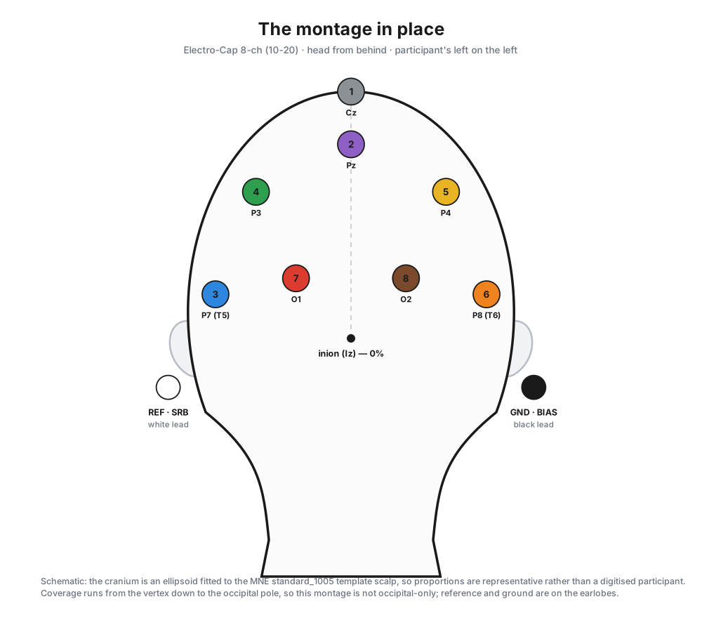
Reference and ground go on the ears¶
This eight-site cap configuration has no REF holder of its own — the midline reference some 10-20 diagrams draw between Cz and Pz is not present. So reference and ground clip to the earlobes, exactly as on the toolbox's other Cyton carriers:
- Reference — the white lead, Cyton
SRB— on the LEFT earlobe (A1). - Ground — the black lead, Cyton
BIAS— on the RIGHT earlobe (A2).
Both are off the visual cortex, so neither carries much of the SSVEP being measured, and an earlobe can be placed identically on every participant without a measurement.
3. Wiring the Cyton¶
Channel colours follow OpenBCI's standard Cyton ribbon-cable order — 1 grey, 2 purple, 3 blue, 4 green, 5 yellow, 6 orange, 7 red, 8 brown. This is the board's convention, not the lab's: anyone who has wired a Cyton already knows it, and it is what the OpenBCI documentation shows.
| Pin | Wire | Goes to |
|---|---|---|
N1P |
Grey | Cz |
N2P |
Purple | Pz |
N3P |
Blue | P7 — the cap's T5 |
N4P |
Green | P3 |
N5P |
Yellow | P4 |
N6P |
Orange | P8 — the cap's T6 |
N7P |
Red | O1 |
N8P |
Brown | O2 |
SRB |
White | reference — left earlobe (A1) |
BIAS |
Black | ground — right earlobe (A2) |
AGND |
— | analogue ground; nothing connects to it |
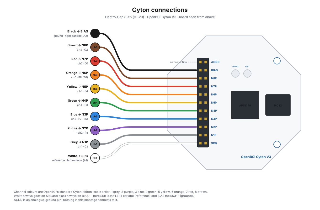
The eleven-pin header runs AGND, BIAS, N8P … N1P, SRB from one end to the other, so N1P is at the far end next to SRB. The board also silkscreens AVDD above the header and AVSS below it; those label separate two-pin sockets rather than positions on this header, and nothing here connects to them.
The reference pin is silkscreened SRB — one name, the one printed on the board you are holding. The header is a double row and we always use the row nearer the board, so the SRB1/SRB2 distinction in the ADS1299 datasheet never has to be made. Reference photo: OpenBCI's EEG setup page.
4. Where it sits in the 10-10 system¶
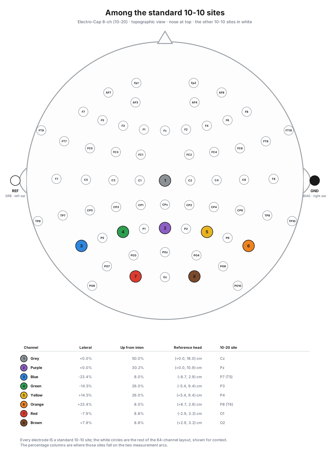
Every electrode is a standard site; the white circles are the rest of the 64-channel layout, for context. The spread is the point: this figure is the clearest statement of both what the montage buys (the vertex, the parietal row, the temporals) and what it costs (six of the eight discs sit outside the occipital cluster the other two carriers fill).
5. How the montage reaches the toolbox¶
| Thing | Where |
|---|---|
| The montage | builder.electrocap_8ch_montage() |
| Carrier name | builder.ELECTROCAP_8CH_HEADSET |
| The sites | builder.ELECTROCAP_8CH_SITES |
The T5/T6 display names |
builder.ELECTROCAP_8CH_LEGACY_NAMES |
| Wire colours | builder.CYTON_CHANNEL_WIRE_COLOURS |
| Reference / ground | builder.headset_reference_ground() |
In a recorded manifest each channel carries its site as its label, and a position_2d reused from builder.acticap_64ch_montage() so this montage, the 10-10 montage and the 64-channel cap plot identically rather than drifting apart in three hand-typed tables:
There is no position_pct — see the note in §1. There is no T5 anywhere in a recording either — see the other note in §1.
Selecting it on Build Protocol → Set up acquisition hardware (or correcting it per session on Set up Session) derives the electrode type — tin (Sn), the recessed tin discs an Electro-Cap carries, used with conductive gel — and the ear reference and ground automatically. That electrode type shares the passive-with-gel mains-noise profile (ssvep.runtime.signal_quality, warn 40 / bad 100) with sintered Ag/AgCl and flat-ring electrodes; no tin-specific calibration is claimed, and one can replace it when there is pooled data to calibrate against.
6. Regenerating the figures¶
The four SVGs in docs/figures/montage-electrocap/ are generated, not drawn. One run produces the figures for every montage the toolbox ships:
A figure drawn by hand would be a second copy of the montage table, and the second copy is the one that goes stale. tests/test_montage.py::test_figures_are_up_to_date_with_the_montages re-runs the script and fails if any figure changes.
Figures 3 and 4 need an actual head to draw on, so each site is placed on an ellipsoid fitted to MNE's standard_1005 template scalp and projected from there. This montage is what first pushed that machinery past the occipital pole: the tape-measure search had a 45 % ceiling on the midline and an 85 mm reach out from it, which was enough for two occipital arrays and silently wrong for Cz (returned as 45 % instead of 50 %) and for P7/P8 (no candidate found at all, returned as the midline). Both limits now clear the whole head, and the search raises rather than returning the edge of its own window.
See also¶
- Occipital 10-10 montage — standard sites like this one, but all eight over visual cortex. The toolbox default, and the right pick for an SSVEP run.
- Free electrode occipital SSVEP montage — the densest of the three over the occipital pole, at the cost of standard site names.
- Impedance check — the Run-mode electrode check that plots this montage.
- Protocols and sessions — where the carrier is chosen and stamped into a run.
- BIDS conversion — where
referenceandgroundbecomeEEGReference/EEGGround.